
How to make 12v and 10amp power supply easy with circuit diagram
This is the circuit diagram of 12V / 10A switching power supply. The circuit, shown in the schematic, provides 12 volts, at 10 amperes, maximum, using a discrete transistor regulator with an op-amp functioning as a comparator in the feedback circuit. The supply was constructed in 1984 and is variable frequency, as opposed to the pulse width.
12v Switching Power Supply Circuit Diagram
The final output of this circuit is 12V, and it can deliver 1A: Notes on the Circuit Vin is a 100-300V AC mains connector. MOV is a metal oxide varistor, used to protect the circuit from high voltage spikes. D3 is a full-wave bridge rectifier, and the DC output appears across capacitor C2.
12V 10A switching power supply (with schematic and explanation) YouTube
The corona equipment used in this research includes a high voltage power supply Heinzinger LNC 10,000-5, where both electrodes are connected for positive DC discharge up to 6 kV, which produces a.
12V 3A Power Supply Circuit Using 2N3055 Transistor
The amount of current you can push through your circuit is determined by the total resistance of the circuit and the electrical pressure (Voltage) applied. So, you connect your circuit to a 12V battery and lets say 100mA of current flow through the circuit and all is well. you are still only applying 12V of pressure.
12V 8A 100W Switching Power Supply Board ACDC Circuit Module WXDC2412
Figure 1. Switching Power Supply Schematic (20W/12V) Ⅲ Circuit Composition of the Switching Power Supply. The main circuit of the switching power supply is composed of an input electromagnetic interference filter (EMI), a rectification and filtering circuit, a power conversion circuit, a PWM controller circuit, and an output rectification and.

12V 50A 600W power supply schematic & how does it work YouTube
The most commonly used type of power supply circuit is the SMPS (Switching Mode Power Supply), you can easily find this type of circuits in your 12V adapter or Mobile/Laptop charger. In this tutorial, we will learn how to build a 12v SMPS circuit that would convert AC mains power to 12V DC with a maximum current rating of 1.25A.
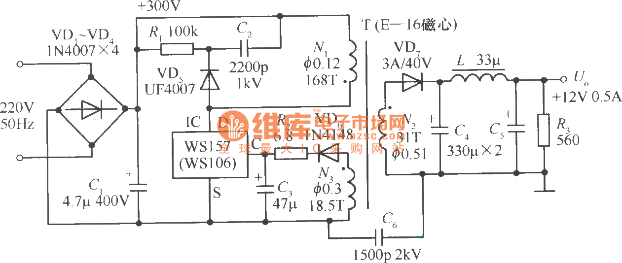
+12V, 0.5A single chip switching power supply circuit Power_Supply
There are two main types of power supplies: The Linear power supply is widely used. It is simple because circuits are not too complicated. But they are large and low-efficiency, at only about 50% or more. While they work, most energy lost is in the form of high heat.

12v 3a Power Supply Circuit Diagram
Generally speaking, a 12V DC power supply circuit diagram will include a power source (a battery, solar panel, or AC adapter), a switch, a resistor, a capacitor, and a voltage regulator.
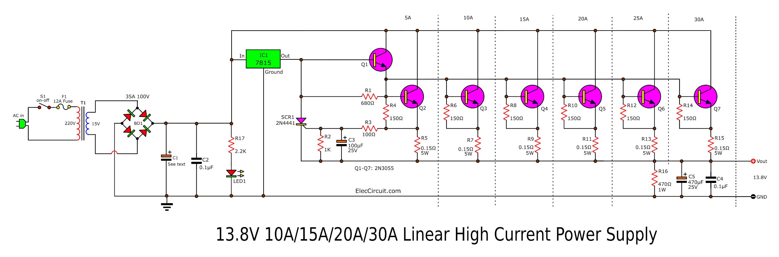
High Current 12V13.8V at 30A,25A,20A,15A Power Supply Elec Circuit
Circuit Protection. Passive Components. Sensors. Connectors. Wire & Cable.. Switching Power Supplies AC/DC Power Supply 65W 12V 5.45A Pin Type TEPS65F12; Cosel; 1: $94.28; 3 In Stock;. Switching Power Supplies 636W 12V 53A w/350% peak power capability HRP-600N3-12; MEAN WELL; 1: $189.48;
12 Volt 20 Amp Power Supply Circuit Diagram
Dual Power regulator +12V/-12V using 7812, 7912. 24V 2A supply circuit Diagram. 18V DC voltage regulator using 7818. 5V Low Dropout Regulator Circuit using transistor and LED Make 5V low dropout regulator circuit using transistor and LED lowest voltage input is 6V so across it is 1V only, make output is 5V 0.5A.
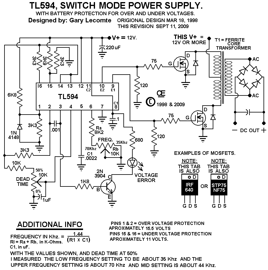
TL594 12V DC Switch Mode Power Supply Circuit Diagram circuitsanyoutube
Every SMPS circuit requires a Power Management IC also known as switching IC or SMPS IC or Drier IC. Let's sum up the design considerations to select the ideal Power Management IC that will be suitable for our design. Our Design requirements are. 15W output. 12V 1.25A with less than 30mV pk-pk ripple at full load.
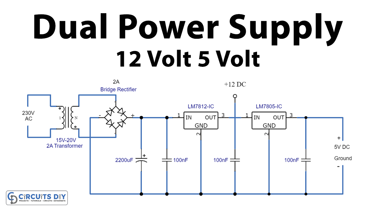
12v And 5v Dual Power Supply Circuit Wiring Diagram and Schematics
The switch-mode power-supply circuits illustrated in this application note provide a ±12V or ±15V at 0.5A output from a 4.5V to 12V input. This wide input-voltage range allows the device to be powered from a regulated DC voltage or even an unregulated DC voltage, such as the rectified output of an inexpensive AC "wall wart" step-down transformer.

12v 10a Power Supply Circuit Diagram
12V 10A switching power supply (with schematic and explanation) 6.4K DiodeGoneWild The schematic in my DB of reverse engineered schematics:http://danyk.cz/reverz44_en.htmlToday I made a.

12V 3A Switch Mode Power Supply EasyEDA open source hardware lab
The following content explains two simple 12V, 1 Amp switch mode power supply (SMPS) circuit using the very reliable VIPerXX IC from ST microelectronics. With the advent of modern ICs and circuits, the age old iron transformer type of power supply are surely becoming obsolete.
12v Switching Power Supply Schematic Diagram Circuit Diagram
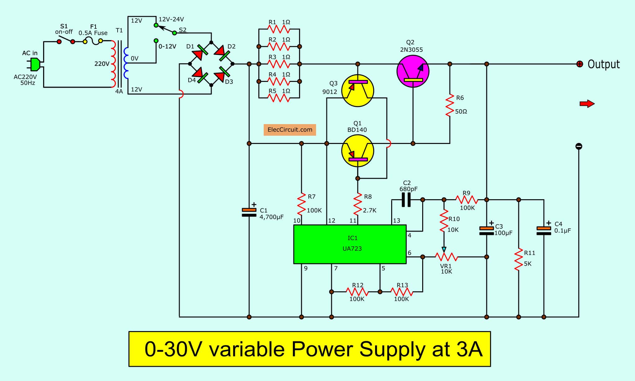
The 12V switching power supply circuit can be created in many ways. Nowadays popular way is to use IC because of its convenience and high efficiency. However, this circuit we are making consists of the transistor and a few parts. Because we want to make great use of old and common components in our inventory. Table of Contents hide

Switching Power Supply Circuit Diagram Headcontrolsystem
The schematic diagram below shows a simple trivial low-cost 12 volt DC 50W off-line SMPS switching power supply circuit. It can be used for DIY home projects or to learn operation of flyback converters. This PSU can work over a universal input AC line range 90-264 VAC. It provides a nominal 12V DC output at more than 4A load.